Security improvement programme
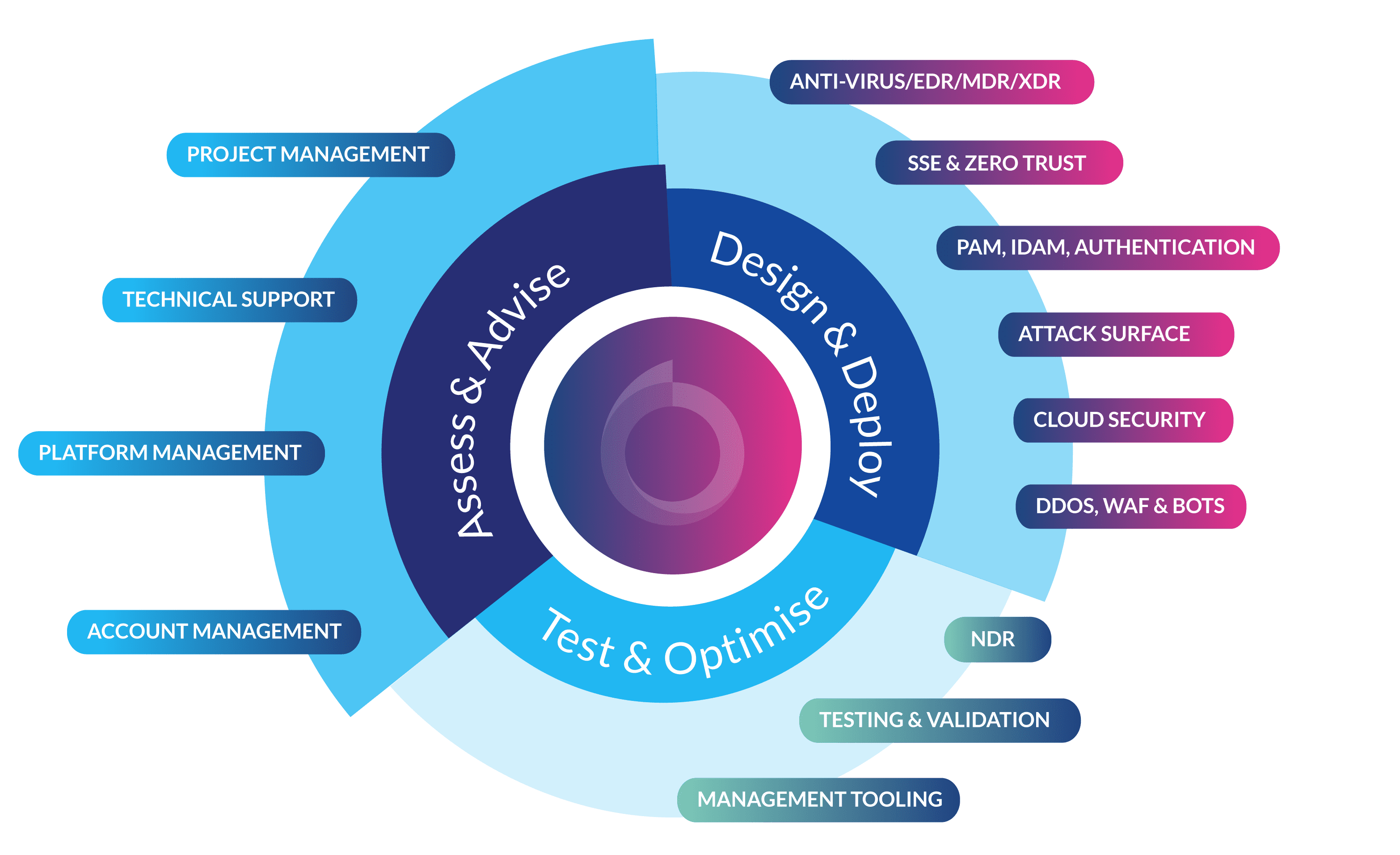
At Babble, our Security Improvement Programme is designed to give you a clear map of your journey to better risk management. Our Cyber Experts work with your Security Teams to identify your key risks and requirements, then walk you through different options for strengthening your security posture.
Babble’s Security Improvement Programme incorporates AI-driven threat intelligence and risk analysis to provide tailored recommendations. We help automate repetitive tasks and streamline security processes, allowing security teams to focus on more strategic initiatives.
We work with several different security frameworks, mapping complementary technology tooling to industry models – all tailored to the specific needs of your business.